Thursday, July 16, 2009

Laser Shaft Alignment


Machines operating in perfect alignment run at their most efficient. Misaligned shafts are recognised as one of the greatest contributors to plant breakdowns, due to the increased forces placed on bearing, mechanical seals, internal components and motor drives.

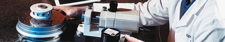
A modern Laser Shaft Alignment system utilises laser-based technology to ensure that the shafts are coupled together along a perfect rotational centreline.

A Laser Shaft Alignment System offers precision alignment of shafts to within hundredths of a millimetre. The latest Shaft Alignment System manufactured by Fixturlaser offers sophisticated laser alignment technology that is fast and easy to operate in the field.

Industrial Applications for Laser Shaft Alignment
Laser Shaft Alignment offers benefits in any industry where rotating equipment applications are used:

  • Direct drive Fans
  • Motor-driven Pumps
  • Gearboxes
  • Compressors
  • Turbines
  • Transfer boxes
  • Propeller shafts
  • Couplings
  • Conveyors
  • Generators
  • Mixers

Common Industries that utilise Laser Shaft Alignment as part of their Maintenance regime include:

  • Manufacturing and processing industries
  • Wind turbines
  • Marine Craft and Shipbuilding
  • Paper and Pulp Industries
  • Water and Waste Water Pumping
  • Construction Industry
  • Gas & Oil Industries
  • Chemical & Pharmaceutical Industries
  • General industry

Easy to use for Express Alignment in the field
The Fixturlaser XA system is characterised by its easy-to-use interface – equally beneficial for alignment professionals using the equipment on a regular basis, and for maintenance technicians conducting periodic alignment checks.

The XA system features a colour LCD touchscreen, with on-screen icons and animated display which guides users through the alignment process.

The XA system utilises CCD digital laser technology, which does not suffer from interference problems in the field, such as bright sunlight, which affect the traditional optical laser systems used by other manufacturer's systems.

Additionally, the XA utilises a line laser (instead of a dot-laser) and a 30mm laser detector in each laser receiver, practically eliminating the need to conduct rough alignment checks.

Pre-assembled fixtures enable the lasers to be attached to the application in seconds, and Bluetooth connectivity eliminates the need for cables from the laser units to the display unit.

The XA system features an Express Alignment mode which automatically samples alignment data once the system is set-up. The net result - Alignment measurements can be quickly and easily conducted in the field in under 5 minutes from opening the lid of the case!

Technologically sophisticated for Precision Alignment

  • Bluetooth (Class 2) connectivity between display unit and laser transmitters
  • Measurement range up to 10 metres
  • 20 hours typical use from rechargeable Li-Ion batteries
  • Slim laser units: 79mm x 77mm x 33mm
  • 128Mb Flash Storage Memory
  • IP65 rated Environmental Protection
  • Standard package includes:
  • Horizontal Shaft Alignment
  • Vertical Shaft Alignment
  • Softfoot Check
  • Target Values

Expansion packages include:

  • Spacer Shaft Alignment software package
  • Machine Train Alignment software package
  • Offset Shaft Alignment software & fixtures package
  • OL2R (offline to running) software and fixtures package for measuring dynamic movements.


Wednesday, July 15, 2009

Laser Alignment System


A Laser Alignment System
A Laser Alignment System is a precision tool for measuring alignment of machines, rotating shafts & pulley, belt.

The benefits of using a laser based alignment system over the more traditional methods, such as straight edge or clock gauges, is the high level of precision that can be achieved.

Early laser alignment systems where characterised as technically sophisticated items of measuring equipment, costing thousands of pounds and requiring specialist knowledge and training to operate effectively.

A Fixturlaser Laser Alignment System is unique in the industry for its high level of measuring precision, coupled with a user interface that requires little or no training for Maintenance and engineering technicians to operate in the field.

Fixturlaser XA - THE Faster Laser Alignment System
The Fixturlaser XA Laser Alignment System offers a complete express alignment system for quick, easy and precision laser shaft alignment.

Fixturlaser XA, together with all its accessories, expansion kits etc, makes everyday alignment work a lot more convenient.

Thanks to fast and effective handling and precision measuring results, the Fixturlaser XA Laser Alignment System helps to save time and money where ever there is a rotating machine installed.

The Fixturlaser XA laser alignment system is a fully-loaded system for express alignment. The standard system contains all the hardware and software necessary for conducting horizontal, vertical and softfoot alignment. There are also several optional accessories and applications to add to the system for the more specialist alignment applications. The user interface large touchscreen is easy to comprehend and the on-screen icons are self-guiding. Pop-up windows provide exact information required, guiding users safely through the alignment process. No external software for printouts of measurement reports is necessary.

No conventional method of alignment is as accurate and user-friendly as the Fixturlaser XA laser alignment system.

Fixturlaser XA Laser Alignment System - Technical Features
The Fixturlaser XA is filled with innovative technical features, e.g. CCD-technology for better measurement results, animated displays that show you exactly what to do, and wireless connections as an option.

These features combined make the system unique in the market. Other features, such as pre-mounted units and snap-on fixtures for quick adjustment, also contribute to making the Fixturlaser XA very user friendly and fast!

3D color animation for fast results
The whole working process is shown on the screen using simple and distinct colour animation. Figures and arrows show the measurement results and any requirement for realignment. Colour coded symbols simplify interpretation of the results.

Automatic registration of measurement points - Express Mode
For faster measuring, the system automatically registers the three measurement points when you rotate the shaft. We call this Express Mode.

Express alignment check
In order to rapidly determine if there is any alignment problem at all, the system is equipped with an express alignment check function. Only one measurement distance needs to be entered into the system.

Wireless data transfer
In order to avoid the need for cables between the measurement units and the display, the equipment can be complemented with wireless data transfer.

Touchscreen with icons means no confusing terminology
The measurement results are shown on a 6.4 inch back-lit LCD touchscreen. Our new software, which is completely based on distinctive symbols and graphics, makes it easier to learn how to use the system. Since the software does not include any text or difficult terminology, the risk of misunderstandings or misuse is minimised.

Small, thin measurement units with large measurement areas
The measurement units are equipped with 30 mm CCD-detectors with low sensitivity to strong ambient light. Despite this, the units are small and thin, which simplifies mounting in small spaces.

Quick and simple mounting
The fixtures are pre-mounted in the case. Any height adjustments are done quickly by using the snap-on fixtures.

Robust and practical design
The display unit is designed and manufactured to fulfil the high demands that industrial use requires of the equipment. It is made of aluminium and rubber and powered by rechargeable Lithium-Ion batteries. The display unit is also classified for protection class IP 65. By using the built-in support, the display unit can be placed or mounted in different positions, depending on the most practical solution at the time.

Connectability for rapid data transfer and documentation
The display unit is fitted with two USB ports, one master and one slave, for quick and simple transfer to a PC and documentation of your measurement results.


Tuesday, July 14, 2009

Motor Alignment

Motor Alignment

The correct alignment of industrial Motors to their driven units (pumps, gearboxes etc) is of critical importance in order to maintain plant reliability.
If the Motor is not correctly aligned, the stress placed on the Motor Shaft will cause premature wear and failure of the motor bearings, leading to plant breakdowns, lost production, and the potential safety hazard of fire.

Laser shaft alignment of Motors and driven units in industrial sectors, including:

  • Manufacturing
  • Food processing
  • Mining & Aggregates
  • Foundries
  • Oil & Gas Refineries
  • Pharmaceuticals
  • Chemicals

Motor Alignment for Energy Reduction
Misaligned Motors are a major source of wasted energy. Why? Well if a Motor is misaligned, there is increased friction on the shaft making it harder to turn. Therefore, a Motor will draw more power (i.e. increase its energy consumption) in order to turn its misaligned shaft.

Ensuring that Motors and shafts are correctly aligned will enable efficient operation and reduce the energy consumption of the unit.

Motor Alignment Products
The Fixturlaser XA and GO systems are professional laser shaft alignment tools for measuring and correcting motor shaft misalignment in both horizontal and vertical planes.

The Fixturlaser GO is an affordable system for site engineers to quickly and easily complete precision vertical and horizontal Motor alignment.

The Fixturlaser XA System is the leading professional laser alignment system for completing precision measurement and alignment of Motors.

In addition to horizontal and vertical motor alignment applications, the Fixturlaser XA system can be expanded with the Fixturlaser OL2RXA Expansion kit to conduct the alignment of Motors that are affected by dynamic movements, caused when the Motor heats up during operation.

The Fixturlaser XA and the Fixturlaser OL2RXA Expansion kit enable measurement of Motor Alignment in both cold and hot conditions and find out the machine’s unique target values. By utilising these values, shaft alignment can be conducted by aligning according to recommended tolerances.

Measurements of dynamic movements are used for critical machines within industries, where large temperature differences or other disturbing factors exist. The need for dynamic measurements is indicated by a high level of vibrations. These high levels remain even after having performed shaft alignment in cold condition. There can be a situation where two identical machines behave totally different, even though OEM recommendations have been taken into consideration, during the Motor Alignment. In order to obtain unique and exact target values, measurements in both hot and cold condition have to be performed. Thereafter, the difference is used as machine unique target values for precision Motor Shaft Alignment.


Monday, July 13, 2009

Prop Shaft Alignment


Prop Shaft Alignment

The alignment of engines and propeller shafts is critical in shipbuilding and marine maintenance, where the stresses and vibrations created by rotating misaligned shafts will not only lead to breakdowns in the engines shaft assembly itself, but can also result in damage to struts and hulls, leading to leaking and possible sinking.

Unlike land-based driven shaft applications, boats and marine craft are not rigid structures, and are subject to twisting forces as a result of environment and load, all of which will affect the mounting of engine and propeller shaft. Boat engine drive systems do not indefinitely remain in alignment and need to be periodically checked and realigned to reduce wear to drive train units, components, and the craft itself.

The Fixturlaser range of Prop Shaft Alignment Systems which have been specifically developed for measuring and correcting the alignment of driven shafts in marine applications.

Prop Shaft Alignment - Consequences of Propeller Shaft Misalignment
Common problems associated with propeller shaft misalignment include:

  • Escalated bearing wear
  • Bent or broken shafts
  • Drive system vibration leading to transmission damage & failure, engine mounts and the boat hull itself.
  • Structural resonance as a result of shaft vibration leading to loosening of struts
  • Worn engine mounts
  • Rapid wear on universal joints and couplings

Prop Shaft Alignment Systems
Fixturlaser XA Prop Shaft Alignment System

The Fixturlaser XA system is a powerful, easy to use laser guided Prop Shaft Alignment System for checking and correcting alignment in propeller or any driven rotating shaft.

The XA System features:

  • Icon-driven large LCD colour touch screen interface
  • 3D colour animations to guide users through the alignment process
  • Unique line-laser technology and large detector areas for easy set-up and measurement
  • Blue-tooth wireless connectivity between laser heads and display unit eliminate the need for cables to transfer data
  • Precision Alignment measurements to within 1/100th of a millimetre
  • Live onscreen measurements instantly inform users of effects of shimming and corrections to engine or shaft position.

Fixturlaser Centring System - measurement of inside diameters
The Fixturlaser Centering System is a Flexible Geometry Measurement system for measurements on inside diameters. It is a powerful tool for checking bearings journals as well as positioning of support bearings in applications such as propeller shafts.

The Fixturlaser Centering measures the rotational centre position, in two axes, in relation to user defined reference points for Prop Shaft Alignment.

The system is based on the Fixturlaser Geo Platform and provides full functionality for measurement, alignment, and documentation. The rigid fixtures together with easy operated components fulfil the requirements on a quick, easy, and precise alignment system. Alignment of bearing journals in diesel engines within shipbuilding and power generation with the Fixturlaser Centering has proved to be most useful.

Technical specification of the Fixturlaser Centring System:

  • Displayed measurement result resolution: 0,001 mm (0,1 mils)
  • Operating temperature range: 0 - 40°C (32 - 122°F)
  • Power supply: All units run on standard batteries.
  • Operating time: Depending on operation cycle 10 - 20 hrs
  • Measurement diameters: 80 - 350 mm (3,15" - 13,78") with standard equipment.

Sunday, July 12, 2009

Roll Alignment

Roll Alignment

Roll Alignment, specifically, is the alignment and measurement of roll parallelism in plant machinery that is typically used to feed sheet materials. Typical industrial applications include:

  • Paper and Pulp manufacture
  • Printing Works
  • Textile Mills
  • All types of Sheet Manufacturing

Problems associated with the misalignment of Rolls include:

  • Drift and tracking of sheet materials during feed
  • Wrinkling and Breakages in paper / material
  • Uneven gloss rate in paper manufacture
  • High scrap rates of materials

Roll alignment is conducted using sophisticated Laser Alignment Systems, such as the ROLL200 laser alignment system produced by Fixturlaser. Fixturlaser systems are widely regarded throughout industry as the most professional, high precision, user-centred systems available.

Industrial Applications for Roll Alignment
The Headbox:

  • Measurement of straightness of the headbox lip profile
  • Measurement of parallelism between the headbox and breast roll

The Foil Section:

  • Measurement of the flatness of the foils

The Press Section:

  • Measurement of the horizontal parallel alignment of the press rolls
  • Straightness measurement of the press rolls
  • Check of the deflection-compensating rolls

The Dryer Section:

  • Measurement of horizontal parallel alignment of the rolls

The Calendar:

  • Measurement of horizontal parallel alignment of the rolls

The Winder:

  • Horizontal parallel alignment of the Tambour rolls

The Coating Section:

  • Horizontal parallel alignment of the rolls

Roll Alignment Systems
The Fixturlaser Roll200 is an innovative laser alignment system providing advanced measurement capabilities for paper machines and other roll applications. The system is easy to use for measurement and alignment as well as for documenting the results.

The Fixturlaser Roll200 is built on the same platform used as basis for other Fixturlaser alignment systems. The Fixturlaser Platform offers the advantage of upgradeability to other Fixturlaser products, to provide capabilities for:

Vertical Shaft Roll Alignment

  • Horizontal Shaft Alignment
  • Softfoot Measurement
  • Straightness Measurement
  • Cardan Shaft Alignment
  • Levelling Measurement
  • Flatness Measurement

Fixturlaser Roll Alignment System Benefits
The Fixturlaser Roll200 features:

  • Easy to use and easy to learn. The intuitive user interface guarantees high usability.
  • High accuracy - one micron resolution (1/1000mm)
  • Quick, easy and flexible setup provides access to alignment wherever and whenever you need it
  • Live values on-screen provide constant feedback on roll position as adjustments are made
  • Flexibility allows use of either floor datum or a selected roll as the reference point for measurements
  • Onboard system memory, plus printer and data ports allow complete documentation of every roll measurement

Technical specification of the Roll 200 System:

  • Measuring distance: Up to 50 meters (150 ft)
  • Displayed measurement result resolution: 0,001 mm (0,1 mils)
  • Operating temperature range: 0-40°C (32 - 122°F)
  • Power supply: Standard batteries
  • Operating time: Depending on operation cycle 10 - 20 hrs
  • Weight complete system: 32 kg

Roll Alignment Applications Commonly Found Throughout the Paper Industry
The parallelism of the rolls, both vertically and horizontally, may affect the drift and wear of the felt, the drying capacity of the paper and may cause breakages in the paper. Especially parallelism in the press nip is important or the pressure will be uneven causing problems with the de-watering process.

Benefits:

  • Less scrap due to uniform fibre structure
  • More output due to the possibility to increase production speed
  • Increased time between replacement of wire gives less downtime
  • Less energy consumption due to efficient de-watering

Measurements:

  • Horizontal and vertical parallelity of rolls
  • Roll parallelism has a direct impact on the paper transportation
  • Compensation is made by adjustable rolls, but severe misalignment can result in wrinkles and breakages at the edges

Roll Alignment - Dryer Section
In this section, the problems are similar to the press sections, although we would like to point out the problem with wrinkles and breakages in the paper sheets. The amount of rolls in the web path is large in the dryer section and increases the importance of roll parallelism.

Benefits:

  • Increased uptime
  • Increased time between felt changes
  • Reduced scrap production
  • Increased product quality
  • Possibility to increase production speed

Measurements:

  • Horizontal and vertical parallelism of rolls
  • Straightness of doctor blades

Roll Alignment - Forming Table
In this section, parallelism between the breast roll and the drive rolls is important, or the drift and wear of the wire will be affected. The surface of the paper sheet is affected if the dandy roll is not parallel to the forming table. The pick up roll and the couch roll may cause breakages and wrinkles if they are not kept parallel, and the suction process may be affected. The levelling of the forming table is another important factor in this section, that will especially affect the de-watering pro-cess and the deterioration of the foils.

Benefits:

  • Efficient de-watering process and uniform fibre structure will improve the paper quality
  • Increased de-watering capability gives possibility to
  • Increase production speed
  • Increased lifetime of the wire
  • Reduced energy consumption for the vacuum pumps

Measurements:

  • Flatness measurement and levelling of the forming table
  • Parallelism of drive rolls
  • Parallelism of forming rolls

Roll Alignment - Head Box
It is important that the breast roll is parallel to the apron board. If the air gap differs, it will cause problems with the consistency of the paper. It is also important that the apron board is straight and the slice gap is correct in order to get a uniform output of paper pulp on to the forming table.

Benefits:

  • Uniform paper structure and thickness
  • Reduced rate of scrap paper
  • Increased efficiency in the dewatering process and possibility to increase production speed
  • Reduced risk of breaking the slice tip

Measurements:

  • Straightness measurement on apron board
  • Parallelism between apron board lip and breast roll

Roll Alignment - Finishing Calendars
The parallelism is important in the calendar, both vertically and horizontally, or the roll nip will differ over the roll length. In some calendars, there is a nip offset that has to be considered.

Benefits:

  • Uniform gloss
  • Reduced scrap production
  • Increased time between roll replacement
  • Possibility to increase production speed

Measurements:

  • Horizontal and vertical parallelism of rolls
  • Set calendar nip offset

Roll Alignment - Winders
Poor parallelism between the calendar rolls, the reel drum and spool may create problems with a high rate of scrap paper as a result. Also the paper may drift sideways during the reeling, creating problems with wrinkles and difficulties when cutting the paper.

Benefits:

  • Less scrap paper
  • Increased production capacity

Measurements:

  • Horizontal and vertical roll parallelism

Pump Alignment


Pump Alignment

The alignment of pump shaft couplings and motor drive shafts is critical to ensure efficient running and to reduce the risk of breakdown.

Misaligned pumps and drives result in vibrations and premature wear of bearings, seals and couplings. It is a recognised statistic that over 50% of plant failures are a result of misalignment.

Offset drives and Cardan shafts also require alignment in order to prevent excessive vibrations resulting in shaft and coupling breakdowns.

Laser shaft alignment systems are used as standard in today’s industry for the precision alignment of pumps and drives.

The Fixturlaser XA system is a laser shaft alignment system specifically designed for conducting alignment swiftly and precisely in the field. In addition to the alignment of horizontal and vertically mounted pumps and drives, the standard XA system can expanded to conduct alignment of offset drives and cardan shafts.

Benefits of Pump Alignment

  • Reduced vibration levels
  • Increased meantime between failures
  • Reduced maintenance costs
  • Reduced energy consumption
  • Increased production quantity
  • Improved plant safety

Pump Alignment Products
The Fixturlaser XA system is an expert system for precision alignment of pumps and drives. Despite its sophisticated technology, the XA system has been designed for ease of use, and includes user friendly features such as:

  • Backlit Colour LCD screen for easy viewing, even in direct sunlight.
  • Touchscreen interface for simple navigation.
  • On-screen animations and icons which guide users through completing the alignment process.
  • Pre-mounted fixtures - lasers can be attached straight to the shaft without complicated assembly.
  • Digital CCD laser technology, 30mm laser detectors and line-laser technology – virtually eliminates the need to conduct lengthy rough alignment checks.
  • USB ports for transferring measurement data to PCS - no need for additional software or printers.
  • Express Mode which registers 3 measurement points automatically when the shafts are turned.

Unlike the majority of complex laser shaft alignment systems that are on the market, the Fixturlaser XA requires minimum training, making it perfect for Technicians who may only perform alignment on a periodic basis. From opening the case lid, users can complete alignment measurements in under 5 minutes.

Standard XA System applications and capabilities:

  • Horizontal shaft alignment software and fixtures
  • Vertical shaft alignment software and fixtures
  • Softcheck™ softfoot measurement application for soft foot condition compensation
  • Feet Lock Function - extended adjustment capabilities in base or bolt-bound situations
  • Target Values - to enable compensation for pre-determined alignment targets provided by pump or drive manufacturers.

Pump Alignment for Offset Drives & Cardan Shafts
Cardan shafts are an excellent way of power transmission, when it is impossible to position two machines in line. There is the general misunderstanding, however, that offset mounted cardan driven machines do not require alignment. However, a misaligned cardan rotates with an uneven angular speed over a full turn. This generates vibrations with harmful forces throughout the drive chain. The risks with misaligned cardan shafts are similar to other misaligned machines plus the risks for damages caused by a broken cardan shaft.

The Fixturlaser OffsetXA fixtures, combined with the Fixturlaser XA system, provide you with:

  • Express setup without using the display unit
  • The inclinometers show the exact position of the lasers
  • The Express result and alignment - the illustrations guide you

Conventional alignment methods, such as straight edges, spanner bars, tape measures, and machinist levels cannot provide the needed level of accuracy.

Using the Fixturlaser XA together with the Fixturlaser OffsetXA expansion kit, you can precision align any offset mounted machine as fast as you align any other shafts.

Saturday, July 11, 2009

Shaft Alignment


Shaft Alignment

Motor Misalignment is the leading cause of machine failure - resulting in premature component wear, plant breakdowns, production downtime and expensive repairs.

Shaft Alignment is of critical importance to Maintenance and Engineering teams who need to ensure that rotating plant machinery, such as motors, pumps and gearboxes, are coupled together in perfect alignment to ensure a perfect rotational centreline is achieved.

If there is misalignment between two machines, such as a motor and pump, then the two shafts will rotate in an eccentric fashion, placing undue stresses on the shafts, coupling, and the units themselves. The result of shaft misalignment is inevitably a plant breakdown, normally due to increased wear rates inflicted upon bearings, mechanical seals and other internal components.

Industrial Applications for Shaft Alignment

  • Shaft Alignment of Motors, in manufacturing, processing, mining, aggregates, printing, wind turbines, marine, pulp & paper, power generation, oil & gas, petrochemicals etc
  • Alignment of Industrial Gearbox Shafts, in manufacturing, processing, mining, aggregates, printing, wind turbines, marine, etc
  • Alignment of Industrial Pumps in factories, wastewater, pumping stations, etc
  • Alignment of Propeller Shafts in marine applications.
  • Alignment of Mixer Shafts
  • Alignment of Fan Shafts

Shaft Alignment Products
The fastest and safest way of aligning a rotating machine is by using a laser-based Shaft Alignment system. Professional service technicians use systems such as the Fixturlaser XA and GO systems to perform alignment measurements and corrections in the field.

Fixturlaser systems are characterised by their:

  • easy-to-operate icon interface (minimal training required)
  • precision measurement of alignment to fine tolerances
  • unique line-laser technology which eliminates the need to perform rough-alignment
  • Bluetooth wireless connectivity of laser transmitters / receivers (XA System)
  • Full-Colour LCD Touch screen (XA System)